Hyperloop!
What is the hyperloop?
Most of my experience with the hyperloop comes from he SpaceX competitions. Elon Musk
published a whitepaper
in 2012, outlining a faster and safer way to travel. Advances in the airline industry
are expected make air travel more efficient for longer distances, but there is a gap where
trains are too slow. The hyperloop is basically a train tunnel pulled to a low vacuum. This
reduces drag without being prohibitively expensive, like maintaining a stronger vacuum would be.
He would later create a student competition to design, build, and test scaled hyperloop pods.
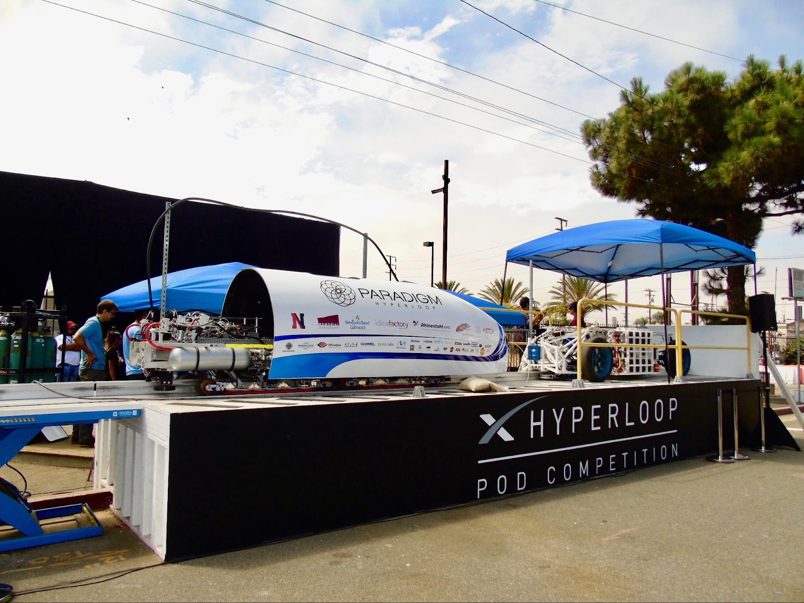
I joined Paradigmin 2016, looking for some more hands on design experience.
Oh man did I get it.
The team had some design and a few builds, but it was pretty clear there was quite a bit of work to do elctrically. The battery system used pouch cells (big no for vacuum), the flight computer interface was unreliable, no power budget had been made, a fraction of the sensors were fleshed out, and other subsystems were non-existent. Most of the sparkys (electricals) had done a co-op or two, but we were not nearly experienced enough for this to be a walk in the park. The team grinded through it all, learning something new everyday. I was fortunate to own a few designs and lead/co-lead the electrical team. I learned more over those ~2 years on the team than in most of my classes combined and made some great friends along the way.
Here's our second place run from Competition II at SpaceX!
The Pod
Let's outline the Pod before getting into design details.

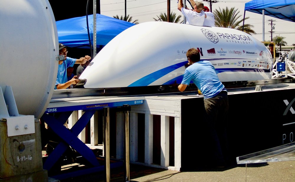
The subsystems evolved over the years but at its core: its 20 feet long, weighs 2000 lbs, and is spec'd to carry another 2000 lbs at 200mph. The levitation system is air based - think of an upside down air hockey table - which creates a cushion of air under the Pod, greatly reducing friction losses. The Pod is autonomous once set to the RUN state, handling navigation, telemetry, and safing itself in the event of an error. Self propulsion wasn't part of the equation until competition III.
There were five core subsystems levitation, braking, electrical, fuselage, software/controls, and air supply. Levitation's primary objective was to ensure the pod has a stable low friction connection to the ground. Imagine being able to push around this 2000lb beast with your pinky. It wasn't quite that easy but it was darn close compared to the team of people needed to push it around on a special dolly. That was the "easier" part of the challenge. Some of the dynamic air flow work the team did was pretty advanced. The pod needs to minimize what I'd think of as oscillations while floating, i.e it can't "bounce" from side to side. It also needs to float sufficiently high such that it can pass sections of the track with small height differences.
The braking team made sure the pod could stop in a safe and controlled manner. Fuselage worked to create a low drag shell, while the air supply team ensured there was sufficient air that was routed safely for leviation and the braking system.
Software and controls had some fun tasks. The pod's brain is a Bealgebone Black, a TI Sitara AM335x based single board computer. It ran all of the state machines, number crunching, telemetry streams, and sensor fusion.
My mindset was that electrical glued it all together. The software can't actuate the solenoids, read a temperature, or even know the pod is on battery power without some clever interfaces. The team's functions were broken up by circuit board:
- MotherBoard: Convert all sensor data onto the SPI bus for the Beaglebone and interface with the batteries
- Batteries+Mangement System: Power the Pod, safely, using a commercial BMS
- ThermoBoard: convert all of the thermocouples into a 0-5V analog signal
- Pusher Interface: Essentially an interlock so the Pod cannot brake while being pushed
- PowerBoard: Smartly switch between ground and battery power + create 24V and 5V rails for the other boards
- LEDBoard: Quick visual status so someone can check the Pod's health+status from a distance
- SSRBoard / Relay board: Array of solid state relays to actuate the various solenoids
- IMU: Really owned by controls but it had to be connected
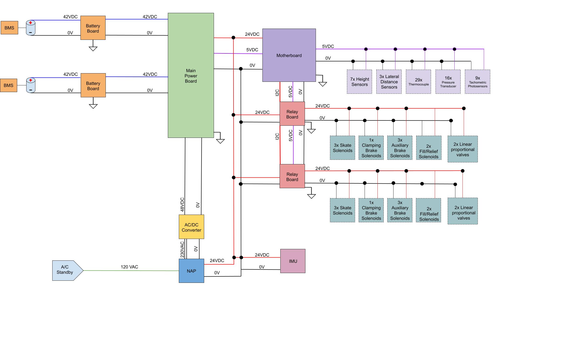
High Level Electrical Schematic

This diagram was revised many times since the modules and system were being designed in parallel. There's two redundant battery packs with an integrated battery management system. The battery boards provide some features so the batteries can be charged. All voltage rails are made by the main power board which switches between ground power vs batteries and will pick the healthiest battery. The 24V and 5V rails are tuned a bit higher for cable losses and local regulation.
The Motherboard handles all analog -> digital conversion, communicates with the IMU and relay boards, and connects to the flight computer. This board is where I spent a significant amount of time - learning everything from how to use KiCAD and good schematic practices, PCB layout, power regulation, A to D, and system design. There are 2-3 revisions on Github and the first one ordered that was DOA hangs above my desk.
The Relay boards consist of a series of solid state relays controlled via I2C. They control the solenoids and proportional valves around the Pod. Later versions of the system have additional boards such as thermocouple interfaces that convert the low voltage signals to a more reliable 0-5V.
